SeaDoo.GTI.repair
How to choose/repair(troubleshoot) the electronics PC Circuit board (CVI) of non-working SeaDoo GTI Sea Scooter with no repair manual.
CONS:
- As one would expect, nobody gives any warranty or assumes any responsability for the results of these hacks.
PROS:
- cheap batteries
- unleash all the power of your GTI
Choose the right seascooter model
I planned to buy initially an Aqua Ranger or Dolphin sea scooters (cheaper than GTI), but after getting feedbacks, I understood that even for very small kids are not strong enough, - and they were right. So the min. version is the GTI.
With the Aqua Ranger money one can buy a 2nd hand GTI, (which, unfortunatelly may turn develop some issues - which we’ll discuss later)
Battery:
Travel note:
- If you plan to travel by airplane, don’t take the battery with you, the airline will not allow your battery, even if it’s dry/sealed Pb battery.
Good parts:
- with ~30$ you can get a new battery from any car battery shop, in any country. I am very happy with it and it was very wise, I saved ~70$ by not getting the original ones, which have identical parameters (sealed/dry Pb battery, same power or even better).
- They are so cheap, you can buy 2, to assure you for a really long day :).
- Myself never managed to deplete a fully charged one in a single day.
Getting fancy:
If you want to be more fancy, get into the Lithuium ones (even SeaDoo started to provide such option for the high end sea scooters). As per my research, LiFePO4 would be the most appropriate, but, you may have other opinion. Here are some options: https://www.aliexpress.com/popular/lifepo4-battery-12v.html . I never ordered them, and I am not aware how they ship them, as airlines rarelly accept batteries, so discuss with seller. The good part is that you have insurance, and if it doesn’t reach you, you get a voucher or something like this with that amount.
Ensure you make the series/parallel arangement such that your voltage is within a Pb battery (11.x - 13.y)
The issue
After a full summer, it stopped working. I checked battery, etc. The contacts are magnetic, so I tried to check using 2 stronger magnets, but no success. (After opening the CVI electronics board, I checked again the magtenic switches (using a magnet) and both were fine: you can measure them, or even listen how the “click”.
HOW TO OPEN
Don’t bother to look in the handlers, there is nothing there, the on/off switches are magnetic (as explained above).
So, let’s find the electronics PC Circuit board (CVI).
Under the battery, there are 4+1 rubbers. The one with a whole in it, does not have any screw underneath, so you may want to leave it as is.
Using a piercing tool, remove the 4 rubbers, and under you will find 4 screws (1-4), just like in the picture below. Unscrew them.
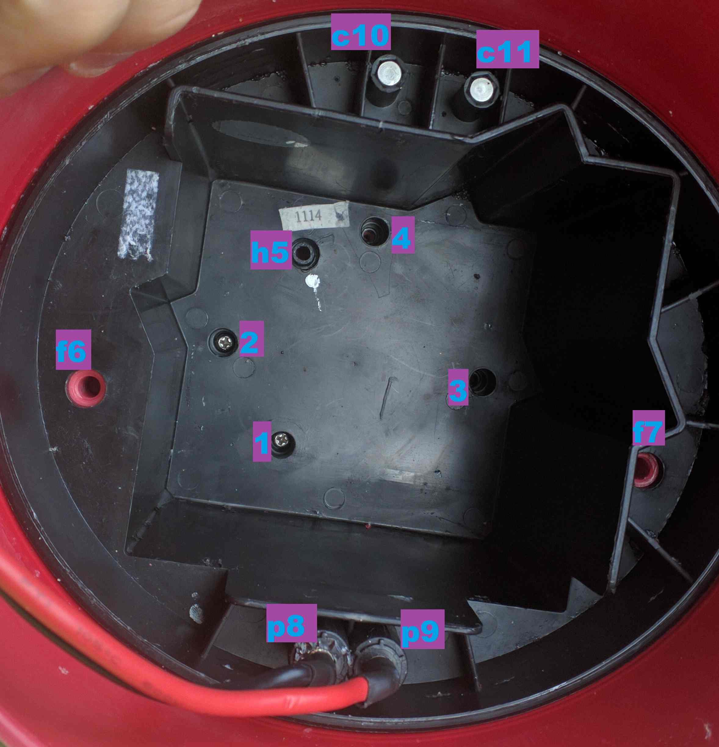
In order to lift up this plastic section, you have to screw two long enough enough screws. They should be 6mm with more fine threads (I guess Pitch 0.75mm). Note, there are 2 types of threads in 6mm screws, choose the fine one. Anyway, you try them, should enter easily if they fit. Screw them in wholes f6 f7 ~1cm deep - don’t force them too deep, ensuring you won’t damage the chasis below. Tie some ropes from both of them, and use a tool to ensure you lift from both sides, keeping the ropes parallel.
Here is the tool I created:
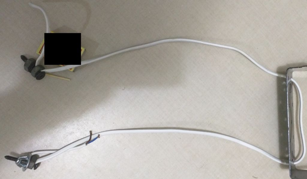
Note the limiters I’ve put, to ensure I won’t screw too much in the f6,f7 wholes.
Even by using this tool, you will have to use quite some force pulling up, you may need someone to help you.
Electronics board (CVI)
The measured current the GTI takes from the battery when running outside of water is 2A. Probably under water it’s more.
The original FET Transistor was a pretty weak one, and probably the board was using the chip on the board to open the transistor with a specific frequency, as opposed to always on (DC like).
This is probably the reason for which, when we used the original transistor continuously (DC), it burned after few minutes of work.
Original FET was: IRL3303 (30V/38A;0.026 ohm) : irf.com/product-info/datasheets/data/irl3303.pdf
We searched for better ones, same package: TO220. Here are some examples:
- IRFB3077P8F
- PSMN1R8_30PL
- AU IRFB8405
- IRLB3034PBF
We managed to find the IRLB3034PBF (40V/195A;0.0017 ohm - way much better than original IRL3303 by all means http://www.infineon.com/dgdl/irlb3034pbf.pdf?fileId=5546d462533600a40153566027b22585)
The HACK
I checked most of the obvious components (fet transistor, diodes, etc), but all are ok. The chances are that some sensor or the logic circuit has issues.
Here is a schematic that removes all the smart (but aparenlty unreliable) part of the board:
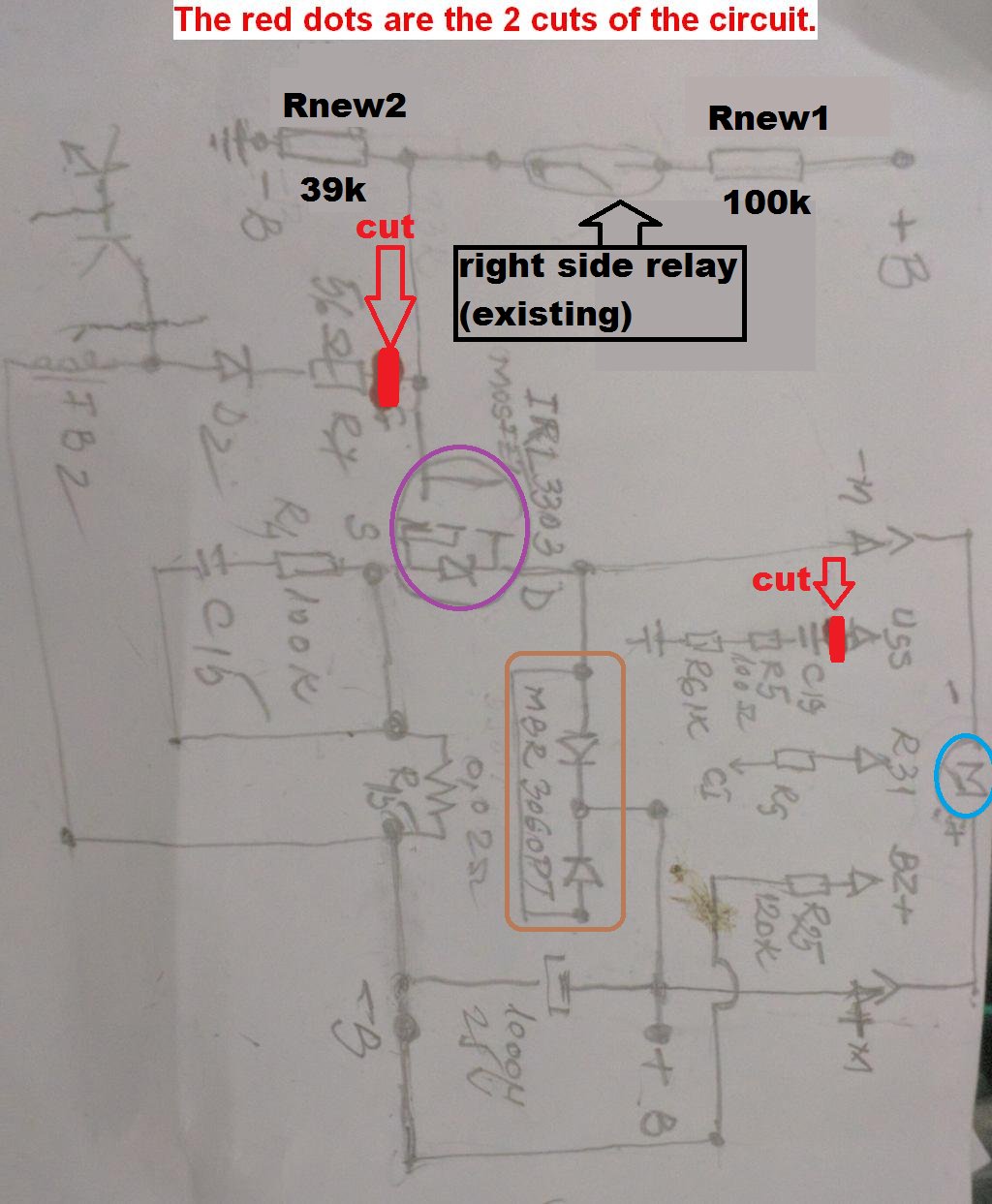
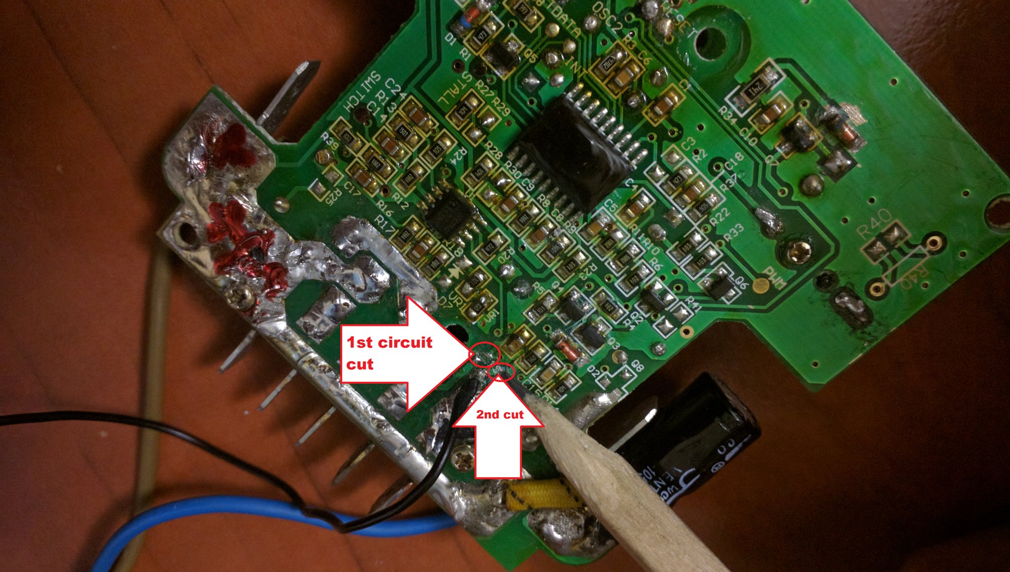
In violet is the transitor, in blue the motor (engine), in brown a protection agains spikes (the engine is a coil and doesn’t like abrupt interruptions :) ) The solution was to simplify the board drastically: disconnect the “smart” part, and keep the part that actually does the work. For this, we have cut the circuit in 2 places. The points can be seen both in the schematic above and in the picture below:
The transistor will get commands from the relay of the right side. Note the two added resistors: Rnew1 (100k ohm) and Rnew2 (39k ohm).
Other images you may want to see:
E.g.
-> the position of the transitor on its radiator (it’s the smaller one, in TO220)
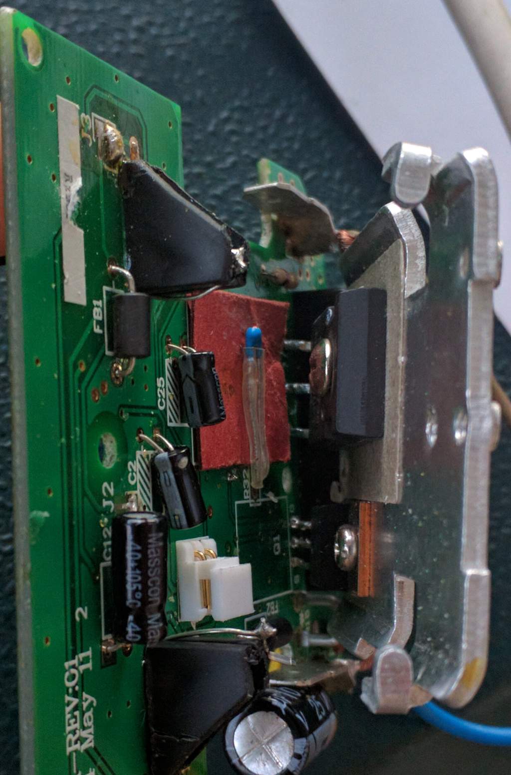
-> the position of the CVI electronics board
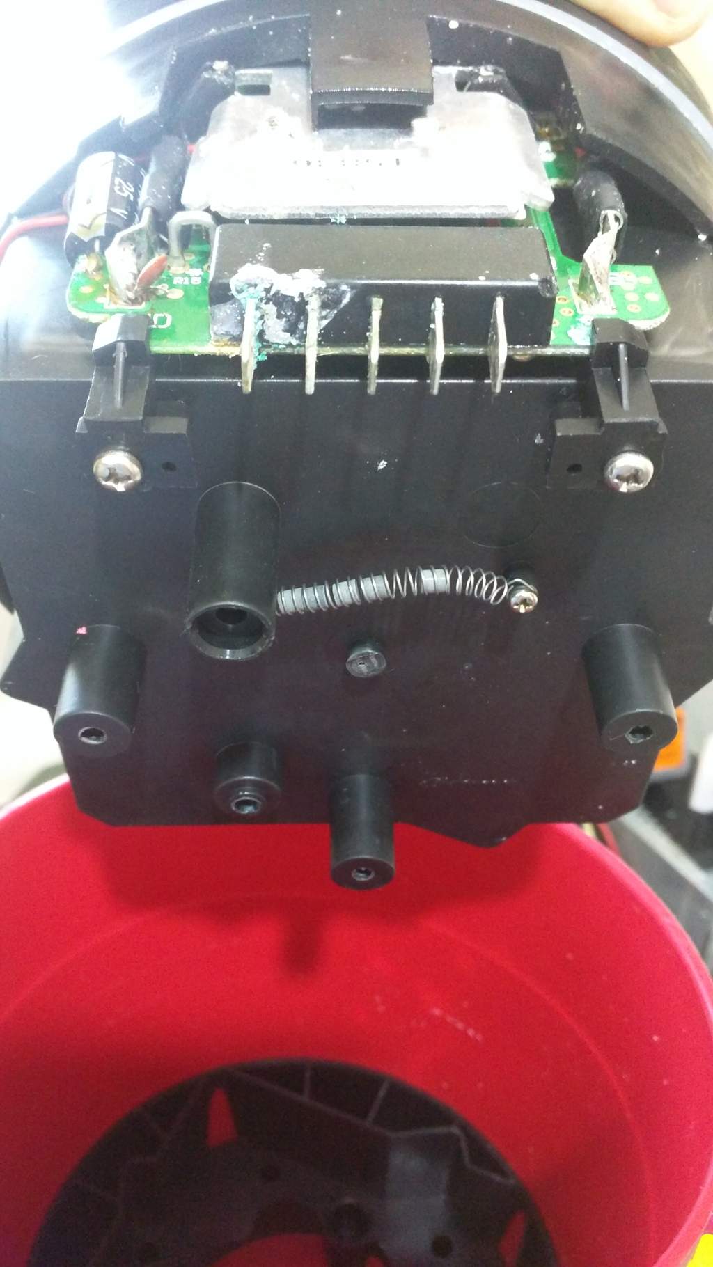
As you can see, some water leaked inside and damaged the connectors. Unfortunately this was not the only issue. Even after proper cleaning did not work, so we proceeded the hack above.
Mounting it back:
When putting it back, put lots of Silicon grease on all the o-rings, to ensure water won’t leak in. Myself I did not find silicon grease, so I used Lithoshield LZ2, which does attack the silicon o-rings, but for now it does the job :). Note: do not use the standard silicon tubes, those are glues that get hard in contact with air, and you won’t be able to open it later on, should you need.
Conclusions:
Cons:
- with the original CVI board, the logic part ensured that the battery won’t finish all of the sudden. It was stopping and afterwards working again, and so on, few times, in order to warn the user that the battery is very low. Now, there is no such warning. For me it’s not an issue, I know that my battery lasts way longer than I am planning to use in that day. Additionally, for really serious people, buy Lithium based batteries.
- the water sensors are disabled. But, I had them enabled and did not detect the water, and it damaged the connectors. So, aparently were not of that great use even before.
Pros:
- Get all the power this engine can give (I find it’s stronger than it was with when the logic part was enabled)
- Get cheap fix, spend your money on something better than a new CVI board:)
Other repair links:
- http://chaa-recovery.ca/wordpress/how-to-fix-a-seadoo-gti-sea-scooter/
- https://www.youtube.com/watch?v=1ZS2H3IPJsg
- https://www.youtube.com/watch?v=QfWPvFvO2-8 (drastically improve power)
Slightly Cheaper parts:
- https://www.aliexpress.com/item/Free-Shipping-300W-sea-scooter-parts-Dual-Speed-Water-propeller-Diving-Under-Water-Scooter-electromotor/32705563155.html (engine from china, 25$ - probably not original )
- https://www.aliexpress.com/item/Free-Shipping-300W-sea-scooter-parts-Dual-Speed-Water-propeller-Diving-Under-Water-Scooter-management-board/32705551622.html (board from china, 35$ - probably not original)
- https://scootermotion.com/shop/seascooter-parts/sea-doo-seascooter-gti-inner-nose-cone-o-rings/
- https://www.ebay.com/itm/331547247084 (silicon grease, 6$ 25gr/0,88 oz )
- McMaster-Carr for orings ( manually check for sizes), something like:
- https://www.mcmaster.com/#9262k835/=19yx7sx - Oil-Resistant (and Water) Buna-N O-Ring: 4 mm Wide, 160 mm ID; 10$/5 pcs (but not tested)